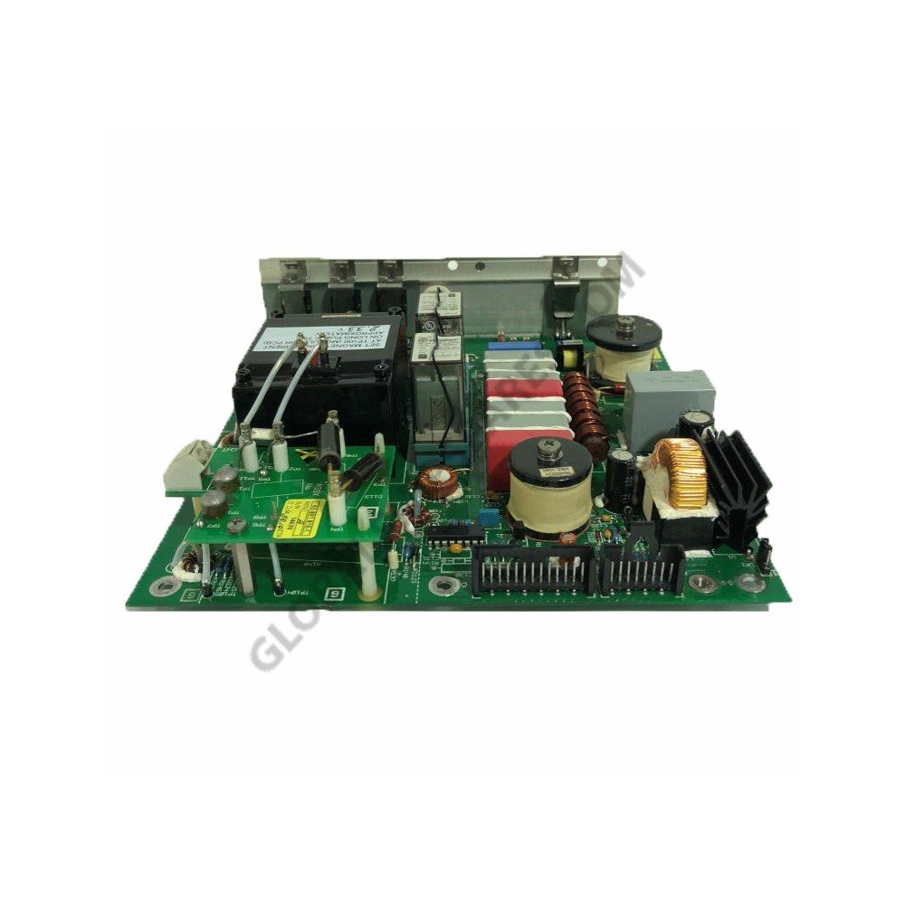
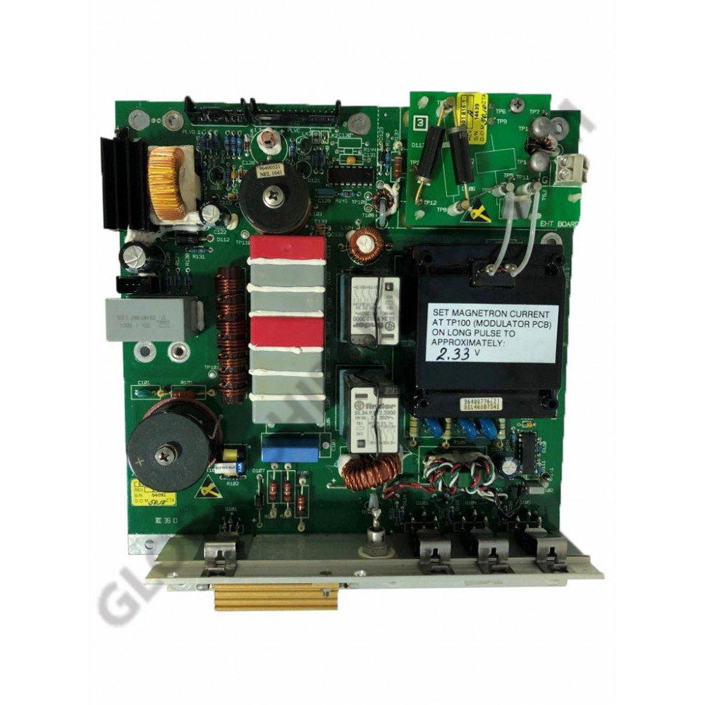
The principal function of the Modulator PCB is to generate an 8kV,8A negative pulse to drive the cathode of the magnetron. An SCR is used to resonantly charge a Pulse Forming Network (PFN) to -1200V from the-600V Modulator HT supply. The Charge Trigger starts the charging cycle. The number of sections of the PFN can be selected by the replays that are controlled by the Pulse Length Control Lines. The number of sections of the PFN used defines the length of the output pulse. At a defined time after the PFN is fully charged it is discharged by three series-connected Insulated Gate Bipolar Transistors through a pulse transformer. The Modulator Trigger starts the discharge. The Pulse Transformer, which has a set-up ratio of 12:1, transforms the resulting pulse to 8kV. A saturable reactor, connected across the primary of the pulse transformer, speeds up the back edges of the medium and short pulses.